Table of Contents
DRAFT - This document is a draft and has not been fully validated.
Typical spring measurement
Introduction
The measurement of the spring is happening after rough measurement (see Doc n° MF4-M21 “Typical spring rough measurements”) and the finishing digging done by the contractor decided on Format n°MF4-F26 (after contract handover). This step must be accurate because its goal is to prepare the bill of quantities that will be attached to the construction contract (last step before construction). It is very important to carry these measurements with the presence of the contractor and his full agreement. This is a time for negotiations and discussion between Woreda construction expert and contractor to help a construction with technical or financial unexpected discrepancies. These measurements could be done during construction transfer.
To help organize this measurement, you have to fill the formats MF4-F21 “Levels”, MF4-F22 “measurement”, MF4-F23 “retaining wall” and MF4-F24 is supporting the others with dimensions and civil work general standards. To carry on these measurements you need a 25m tape measure, a string spirit level, 25m of string (sibago) and 4 pegs. At the beginning, basic information about the site can be checked to be sure that it is still validated after rough measurements:
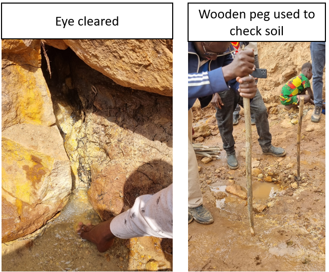
Bottom of the excavation is hard impervious soil (generally rocks or clay), check it with a wooden peg that should not go deeper than 5cm when you try to stab it in the ground
Eyes of the spring are cleared (clearly visible and water flowing on impervious)
Upstream side of the excavation is 2m high at least (for catchment protection)
Accurate positioning of pegs
Span location
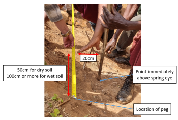
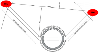
The span pegs (left and right cutting walls limits) should have been installed during rough measurement. Now that the eyes have been finally cleared by contractor they should be installed again with more accuracy. Imagine that the future cutting walls should have a clearance of 20cm with the right-most and left-most eyes of the spring downward. With this wall direction set, the peg should be installed 50cm after the eyes (1m or more for wet soil). Those pegs represent right and left finishing points for the cutting walls and the limits of the catchment area (cover slab).
Box location
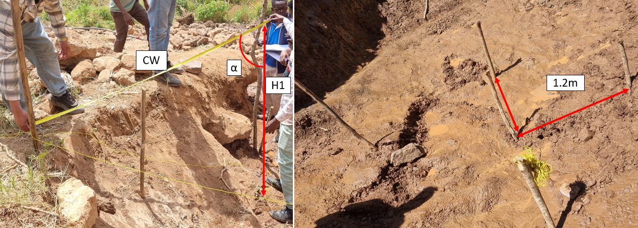
The same approach apply for the box location. Check that the peg representing the center of the box is well located in a suiting area (flat, stable with 2.3m area available for construction). Then with a 1.15m rope install for pegs around the center of the box to materialize the top, bottom, right and left limits of the box foundation.
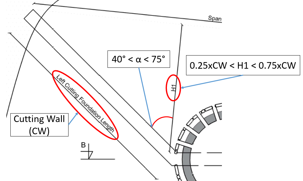
The perfect location of the box is as close as possible from the eyes (to limit cover slab and retaining walls dimensions and cost) while keeping the angle of the cutting walls and H1 between 40 & 75° (To avoid expensive structure geometry or water getting out of the catchment).
A simple way to ensure that is H1 (measure between span line and center of the box) is bigger than 0.25 times cutting wall dimension but smaller than 0.75 times cutting wall dimension. This measures have to be taken at the right and left limit of the box foundation. This allow to experiment several locations to find the best one (as close as possible from the eyes while respecting angle limitation).
Cover slab limit
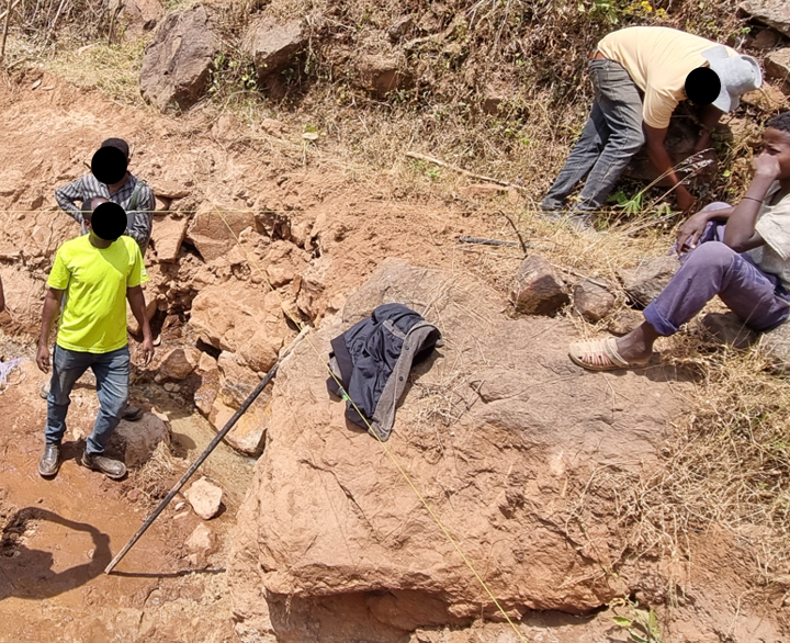
To find the cover slab end use the same method as in Doc n° MF4-M21 “Typical spring rough measurements” § Cover slab end, as a beginning point of discussion with the contractor (20cm above the eye in front of the box and beyond the eye until the ground is touched). The final position agreed should be a balanced position between construction logic (keep a standard geometry for the slab) and economic logic (minimum cover slab dimension).
Measurements
Distances
Once all the pegs positions described above have been installed, formats can be filled. Beginning with MF4-F22 “measurement”:
Most of the measures in this form are the same that the one described in Doc n° MF4-M21 “Typical spring rough measurements”:
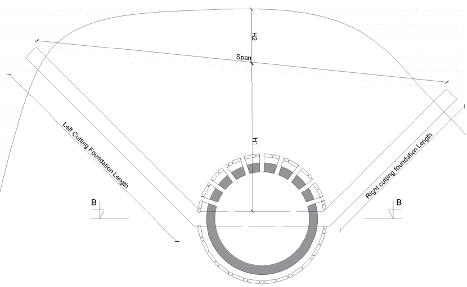
- Span is the length between the end of cutting walls pegs (use a sibago to materialize it)
- H1 is between center of the box and the span sibago (use a straight stick to extend box center peg for an accurate and parallel measure)
- H2 is between span sibago and end of cover slab (keeping direction toward center of the box)
- Cutting foundation length are a little bit different because it has to be taken from left and right limit of the box foundation to the span pegs instead of the center
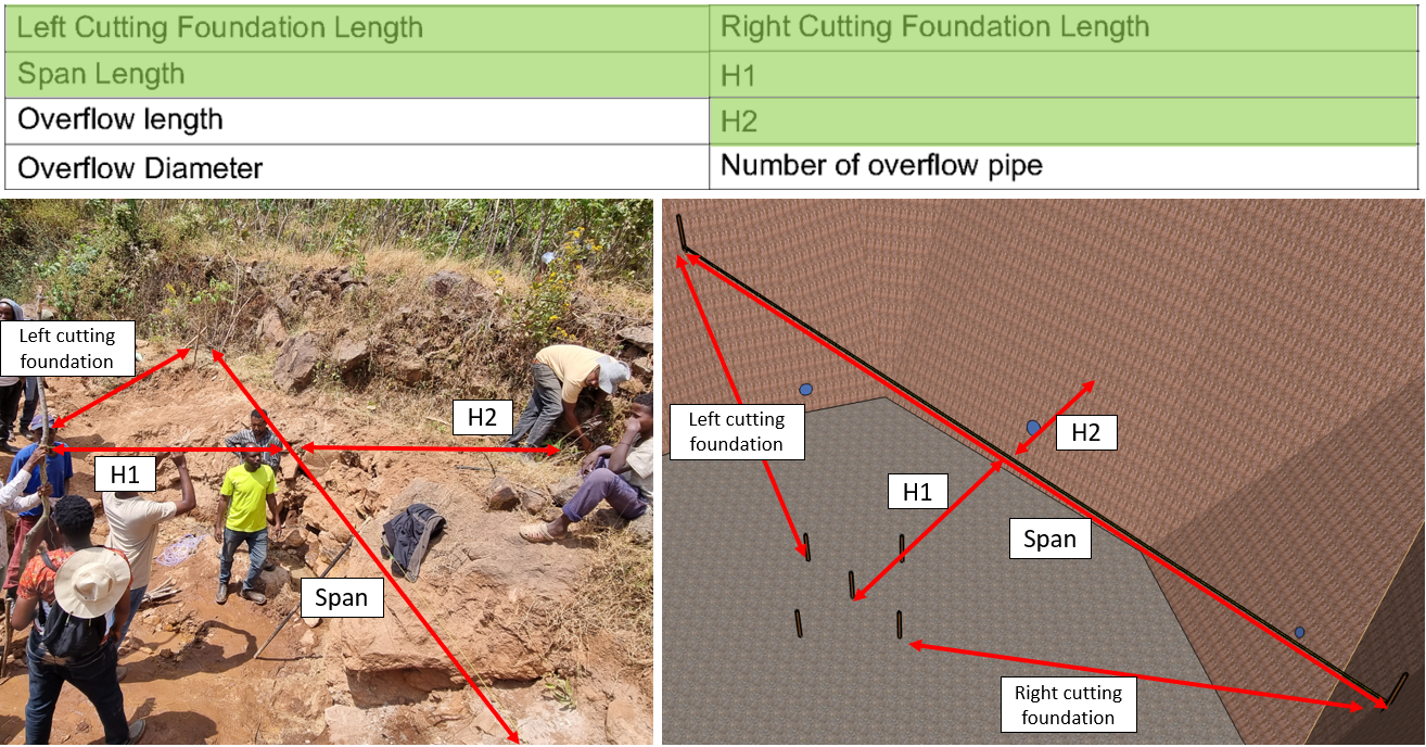
The previously set overflow spillage point should be checked in comparison with the new position of the box (if changed). As a reminder, this point should have a slope to evacuate water, not over future pipeline and as close as possible of the box (this length is asked in the form). To finish, use the spring yield (given in the network design sketchmap) to set diameter and number of overflow pipes.


Levels
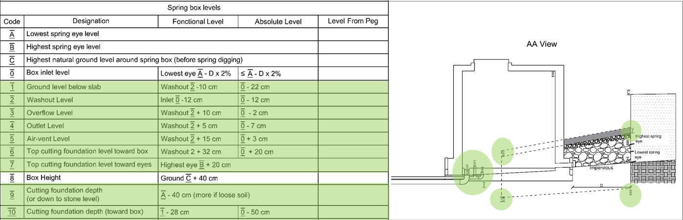
MF4-F21 “Levels” is designed to check the position of the box for level, discuss the level of all the future structures with the contractor and set the height of the box (1, 2 or 3 rings).
Box inlet level is the “point 0” of the whole structure, it is materialized by the ground level at the top of the foundation box peg. All other construction levels are expressed compared to it, contractor should mark it and remember it.
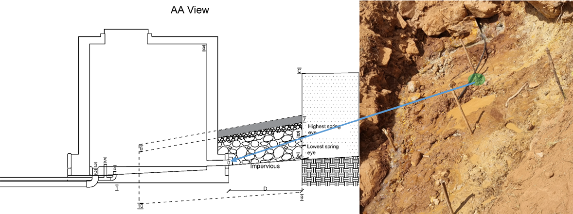
Most important point of the form is to check the slope between highest/lowest eyes with box inlet level to avoid backflow or stagnant water in the catchment. This slope must be at the minimum equal to 2%, so the height of the point 0 is less than A-Dx2%. For this, use a string spirit level to compare eye level with the ground at the top of the box peg.
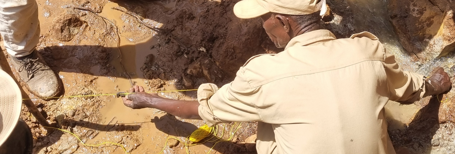
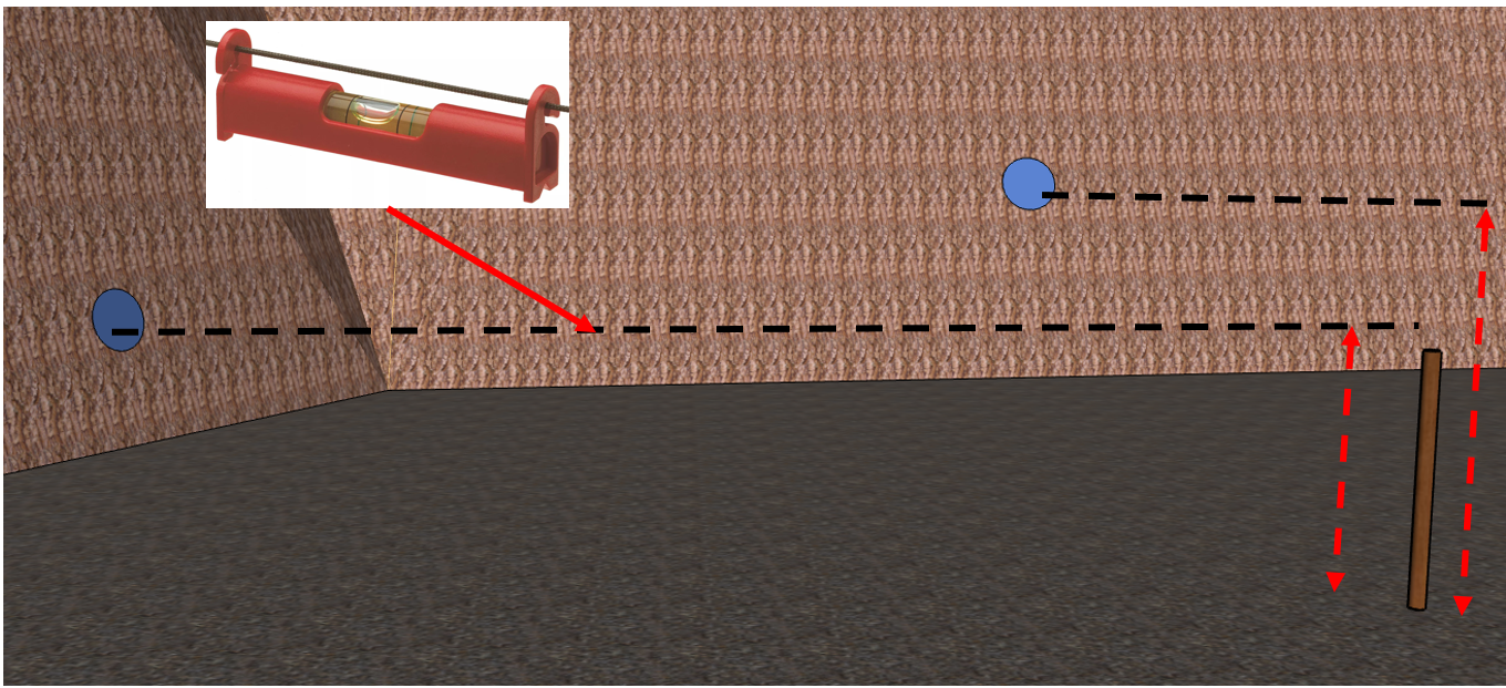
Then the surrounding ground level at box location using the same method as in Doc n° MF4-M21 “Typical spring rough measurements” § Surrounding measures (sibago parallel to span line above center of the box at natural ground level, measure from box level to sibago). Level 7 is this level + 40cm, it represent the top of spring box (3m maximum).
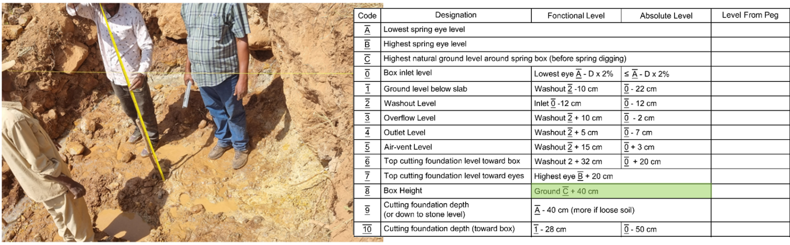
The following levels are designed to discuss them with contractors, if the method Doc n° MF4-M24 “Typical spring box construction” is followed, all these levels will be respected. They are all expressed compare to box inlet level (except cutting foundation for construction logic reasons). Discussing these level with contractor is a way to raise awareness for the contractor:
- 1: Level of box foundation
- 2: Washout level which is the lowest inside the box
- 3: Overflow level is washout level + 10 cm PVC pipe lower than box inlet to avoid backflow
- 4: Outlet level in between Washout and Overflow
- 5: Air-vent level above Washout
- 6: Top of wall toward the box is always the same
- 7: Level of the cover slab toward its upstream limit:
- If the highest eye is less than 50cm above the level 0, 7 is also the top of wall toward upstream limit of cover slab
- If the highest eye is more than 50cm above the level 0, 7 is not the top of wall. toward upstream limit of cover slab, the cover slab will have one or 2 slopes to reduce cost (less volume of concrete in the cutting walls)
- 9: Foundation depth 40cm under lowest eye and 50cm under box inlet level at box level (check construction methodology). Interesting point to discuss with the contractor especially in spring with big slopes (foundation depth all the walls way to find safe and cheap solutions)
Retaining walls
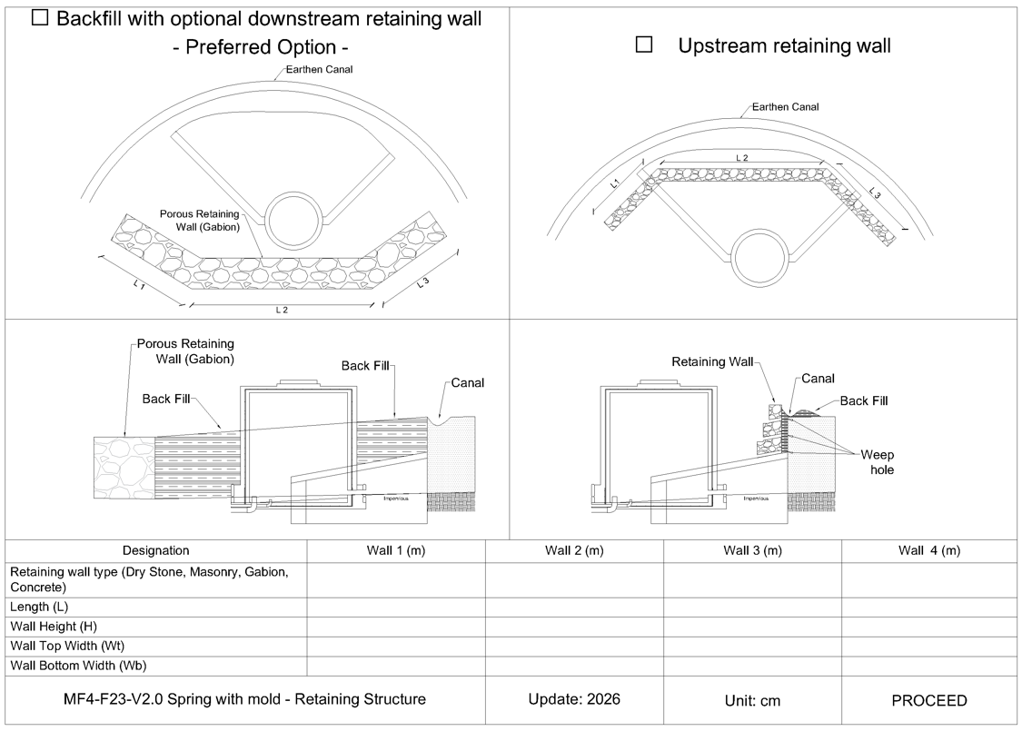
The format MF4-F23 “retaining wall” is a simple confirmation (or not) of the data taken in the rough measurement step but with contractor input and agreement. It is a very important point as over cost for retaining walls are a common problem for spring construction.
Doc n° MF4-M21 “Typical spring rough measurements” § Retaining walls should be used to take the best decision for cost and sustainability of the spring catchment.
These 4 formats (MF4-F21 “Levels”, MF4-F22 “measurement”, MF4-F23 “retaining wall” and MF4-F24) must be updated all along the construction to match the reality (either with red pen on them or done again) with the dates and must be signed by Woreda construction expert and contractor.