

Table of Contents
THIS VERSION IS A DRAFT AND HAS NOT BEEN OFFICIALLY APPROVED
Spring Design Measurement
Prerequisite:
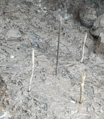
This procedure contains pegs installation to do the measurements (collection box, cutting walls and retaining walls), they should be hammered into the ground to remain in those locations until construction.
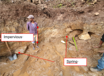
The spring excavation should be completed and checked before any measurements. The following criterias should be met:
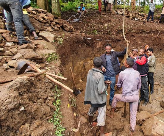
- The surrounding of the spring must be cleared to create a suitable working area
- The excavation should assure that 2m of natural ground above the higher spring eye is present to protect the water from pollution
- The impervious layer must be visible on all the excavation. Ground must be checked by penetrating a thin iron bar (the penetration should be difficult)
- Digging must not be too deep into the impermeable layer, water may seep downward.

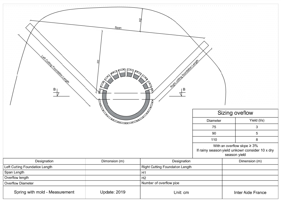
Prepare a printed copy of drawings 1 to 3 for spring measurements. All measurements will be noted in the tables and copy stored with the BOQ file.
Start with the « above » measurements:
Tools needed:
- Measuring tape (~20m)
- 6 pegs
- Long and straight stick (3-4m)
- 10m of rope. More length is necessary for big spring.
- First Step of the spring design measurements is to define center of the collection box :
- Collection box should be downstream of the lowest spring eye and as centered as possible compared to all the eyes position. A flat and favorable ground should be preferred. The center of the box should be at a minimum distance of 1.66m from the closest spring eye. When this position is found a peg should be installed.
Materialize the collection box with 3 others pegs: right, left and furthest point form the spring. Use a rope of 116cm length as a compass to locate those points (radius of the box’s foundation).


To measure the length of right and left cutting wall, you need to find the shortest way out of the excavation starting from right and left pegs of the collection box (while keeping an angle toward the eyes of the spring).
If the soil is dry add 50cm, if it is wet add 100cm and install one peg on each sides.
 Then use a measuring tape between the right and left collection box pegs and the 2 pegs out of the excavation.
To measure those lengths you need a long and straight stick to extend the pegs in the excavation to keep the measuring tape straight;
Then use a measuring tape between the right and left collection box pegs and the 2 pegs out of the excavation.
To measure those lengths you need a long and straight stick to extend the pegs in the excavation to keep the measuring tape straight;


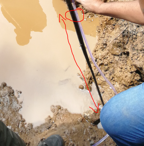
Span length can be measured with the measuring tape between the 2 pegs out of the excavation. Make sure the measuring tape is horizontal. Use a piece of rope to materialize the span line that you’re going to use to find H1 and H2


With a long and straight stick, extend the collection box center peg and measure the distance with the rope materializing the span line (measuring tape perpendicular to the rope). If necessary repeat the measurement for the left and right pegs of the collection box. The longest measurement obtained is H1. H2 is measured between the span line and the furthest upstream point of the excavation (keeping the measuring tape perpendicular to the span line).


To finish with the “above” measurements locate the discharge of the collection box overflow. Install a peg there and measure the length to the box.
With the chart and the spring yield, define the diameter and the number of overflow pipes.
 Measure the span and length of the exca vation for estimation of contractor supervision hours in the BOQ

The second measurements are the levels:

Tools needed:
- Measuring tape (~20m)
- Long and straight stick (3-4m)
- 20m of transparent flexible tube (minimum ⌀ 8mm). More length is necessary for big spring.
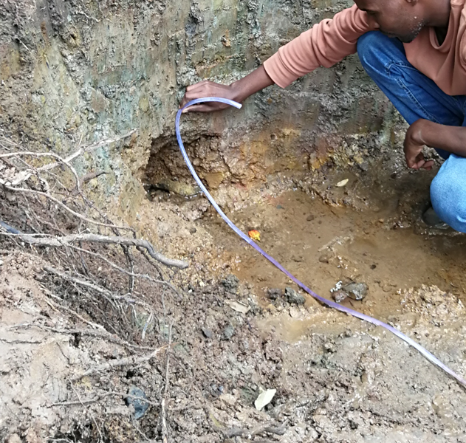
Fill your flexible tube with water by siphoning from a pool or bucket. (Fill the first section with water until there is airlock, immerge one end in the water and the other end outside and lower down and wait until water comes out the low side without any bubbles and close that end then the other by bending the tip if the hose). Check along the tube there is no air bubble trapped. Make sure the hose stays full of water for the rest of the measurements.

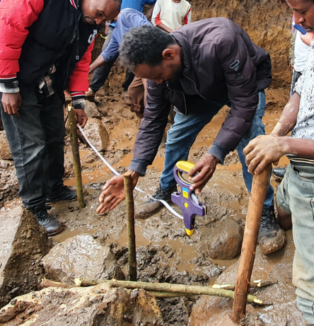
Locate the highest and the lowest spring eyes, the lowest is your “0”, your reference point noted A on the document. Keep in mind that the different eyes can be on different geometrical planes.
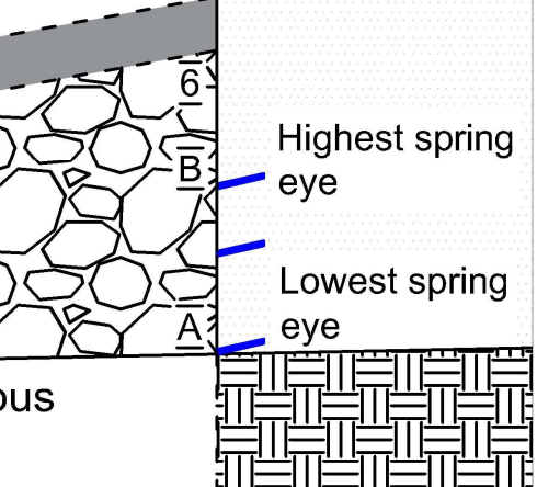 To obtain the B level, place one end of the hose on the highest spring eye. Make sure that water level in the hose is the same as the eye level.
 Place the other end on a stick placed above the lowest spring eye (point A). The difference between water level in the hose and point A have to be measured on the stick, this is your point B measurement.
- To find point C use a long string that is held on a line passing trough the back of the slab being parallels to the back earth wall (the end of the excavation). Level the string to have it at an average between the 2 points of natural soil on each side of the excavation.
Mark this level (point C) and measure the height difference between it and the lowest spring eye.
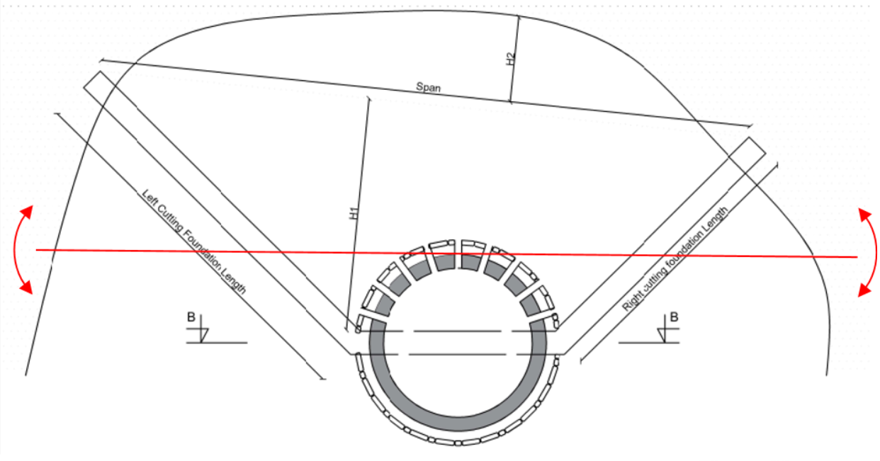
D length is the distance between the furthest upstream point of the excavation and the closest edge of the collection box. To obtain it, measure the distance between the axis materialized by the 3 pegs of the box (using rope) and the furthest excavated point (measuring tape is perpendicular to the box’s axis). Then subtract the radius of the box foundations (86cm) and you have your D length.
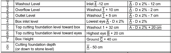
 To finish with level measurement you can calculate all the remaining levels from 0 to 7 with the help of A to D measurements.
The final measurements are the retaining walls:

Tools needed:
- Measuring tape (~20m)
- At least 6 pegs
Below is a rough guideline but keep in mind that the retaining wall really depends on the nature of the ground downstream and above the spring (soil, slope, resources …).
First step is to choose between upstream or downstream with backfill retaining wall option. Downstream + backfill is the preferred option, the reasons for a downstream wall are the slope and/or the instability of the ground above the spring.
Downstream walls:
Determine the position and number of retaining walls needed depending on the geometry of the excavation. The walls should be close to the collection box (respecting a minimum 30cm distance), perpendicular to the direction of the excavation, and their span should be bigger than the cutting walls span. The center wall (L2) length should be 3m, centered on the collection box.
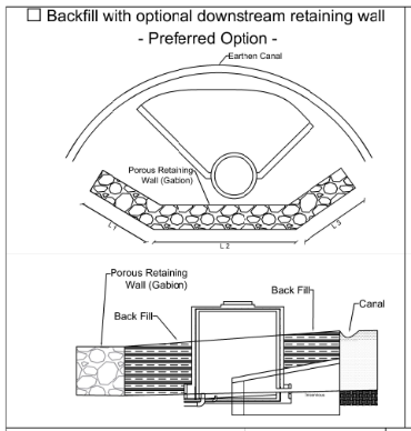
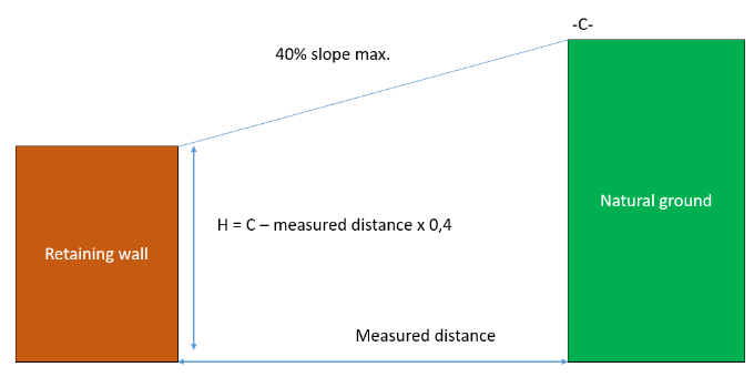
Install pegs to materialize the walls position and measure the distance from the beginning of the excavation (towards spring eyes) to the furthest peg. Determine the wall minimum height with the level of the highest ground (C level) and 40% maximum slope to the furthest peg.
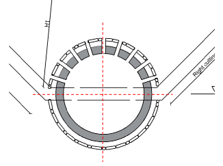
 At the end, the locations indicated in red in the drawing have pegs installed
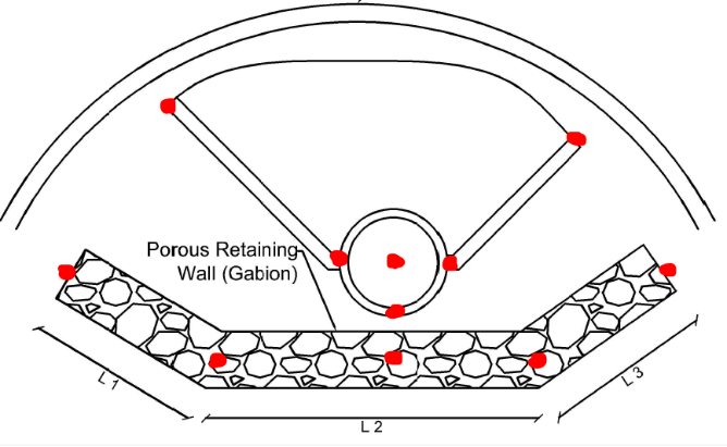
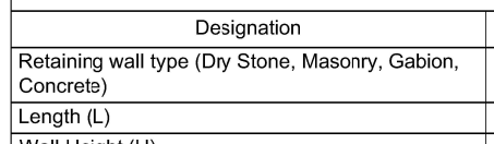
- Choose the type of retaining wall depending on dimensions and availability of resources (the most cost effective solution must be found). Measure the length of the retaining walls between the pegs.
 Upstream walls:
Determine the position and number of retaining walls needed depending on the geometry of the excavation, soil quality and slope. The walls should follow the beginning of the excavation (toward spring eyes), and their span should be bigger than the cutting walls span. Its height should be higher than the natural highest ground. Their width should depend of their height and their type. At the end, the locations indicated in red in the drawing have pegs installed Choose the type of retaining wall depending on dimensions and availability of resources (the most cost effective solution must be found).
Measure the length of the retaining walls between the pegs. £
