

Table of Contents
DRAFT - This document is a draft and has not been fully validated.
Typical spring box construction
Introduction
This methodology describe the construction of a “standard” spring with narrow excavation (consult Doc n° MF4-M23 “Spring excavation” for more details). There is of course no such thing as a standard spring, as the construction depend entirely of the topography and nature of the soil. What we mean by standard is a spring that is composed by a spring box constructed with a reservoir mold, 2 cutting walls and a cover slab (no PVC drainage, multiple boxes, tunnels…). And also not too expensive compare to the network size (consult Doc n° MF4-M21 “Spring rough measurement” for more details).
This methodology is built as a step by step approach, so before applying this construction methodology the following documents and actions have to be implemented in this order:
- Doc n° MF4-M21 “Typical spring rough measurement” to prepare initial BoQ (before contractor selection), validation of the excavation and decision about when constructing the spring
- Doc n° MF4-M22 “Typical spring measurement” for preparation of the construction (visual help and BoQ) and use as a working document during construction
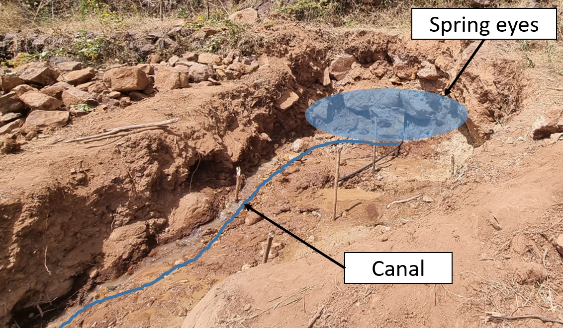
First work on the spring location is to dig a canal to remove the water flowing from the spring eyes without disrupting the future civil work:
Foundations
During the measurement of the spring pegs have been installed in particular at the center of the future box and at the left and right limit of the spring (span). Three 50cm deep excavations (to compare with reference level 0, check Format n°MF4-F21) should be dug and compacted to create foundations of the spring:
- First a 2.3m diameter circle around the center of the box (limit the depth of the excavation at 25cm upstream of the cutting wall)
- And a 20cm wide trench from the left of the box excavation to the left span peg
- To finish a 20cm wide trench from the right of the box excavation to the right span peg
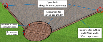
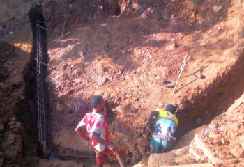
If the soil inside the excavations is not well compacted because of the lose nature of the soil, the digging should be more than 50cm deep and the construction supervisor (WWO expert) should be consulted to validate the future over cost. To facilitate water evacuation, digging and foundation casting can be done one side at a time (water being evacuated on the other side).
Cutting wall
To prepare the casting of the cutting wall, install a 20x20cm mesh of 8mm rebar in the middle of the trenches and the box foundation:
- For trenches: vertical rebar are 110cm from bottom of the trench, horizontal rebar 70cm max above bottom of the trench (at the end vertical rebar should be at least 60cm above ground and horizontal maximum 20cm above ground)
- For box excavation: Mesh rebar 25cm below reference level 0 (ground level at box inlet)
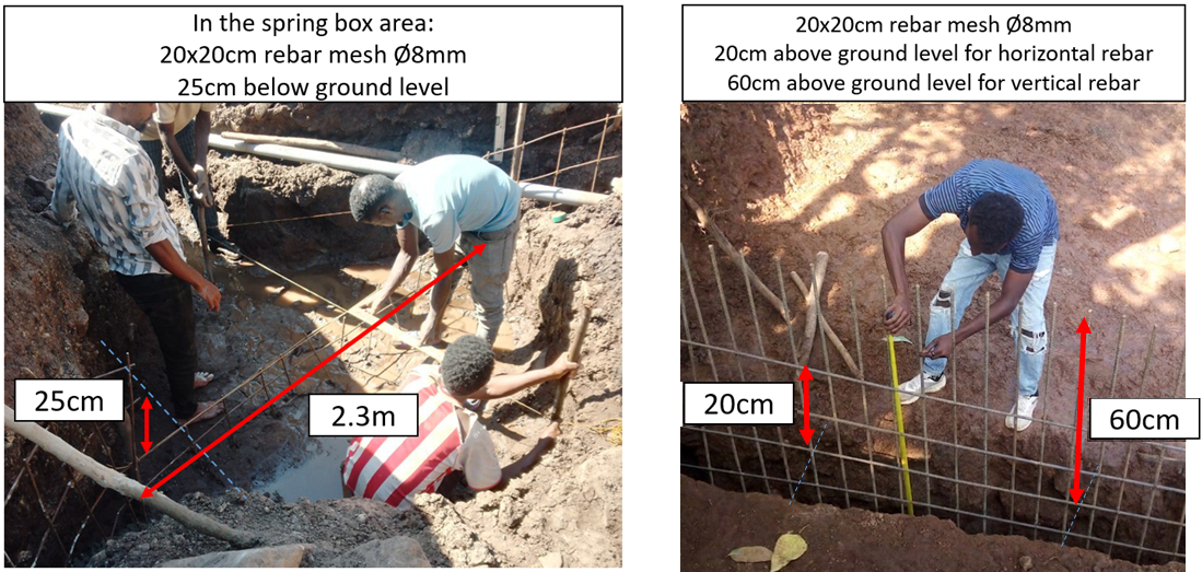
Prepare to cast a wall inside the trenches and 32cm above it using formwork. The wall in the box excavation will be 25cm high using formwork. On 40cm long the trenches walls on both sides of the box excavation should be casted at ground level. This will allow in the future to evacuate the water when working on the box slab and a water tight link between box slab and cutting wall.
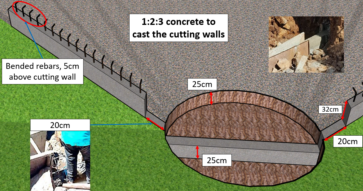
Box slab preparation:
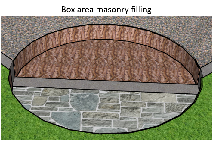
The space left in the box excavation downstream of the cutting wall should be filled at the same level with rough masonry, to obtain a flat surface that will support the concrete slab
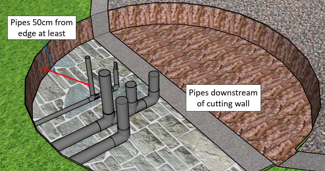
PVC pipes and fitting arrangement should be prepared on the masonry foundation (downstream of the cutting wall) according to the network sketchmap. Consult Doc n° MF4-M40 “Distribution box construction methodology” § Bottom slab casting for more details. The difference with a DB is that the PVC is installed flat on the masonry foundation, not inside as follow:
The installation of the overflow system must respect to the following requirements:
- The overflow pipeline must not cross the adduction line;
- The pipeline must maintain a minimum slope of 3%;
- The distance between the spring box and the end of the overflow must be at least 6 meters;
- Overflow pipe sizing depends on the dry season yield;
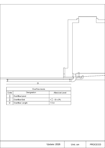
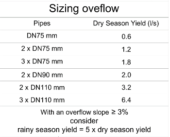
Check Doc n° MF4-M10 “Standard construction items” § Washout erosion protection structure for more details.
Slab
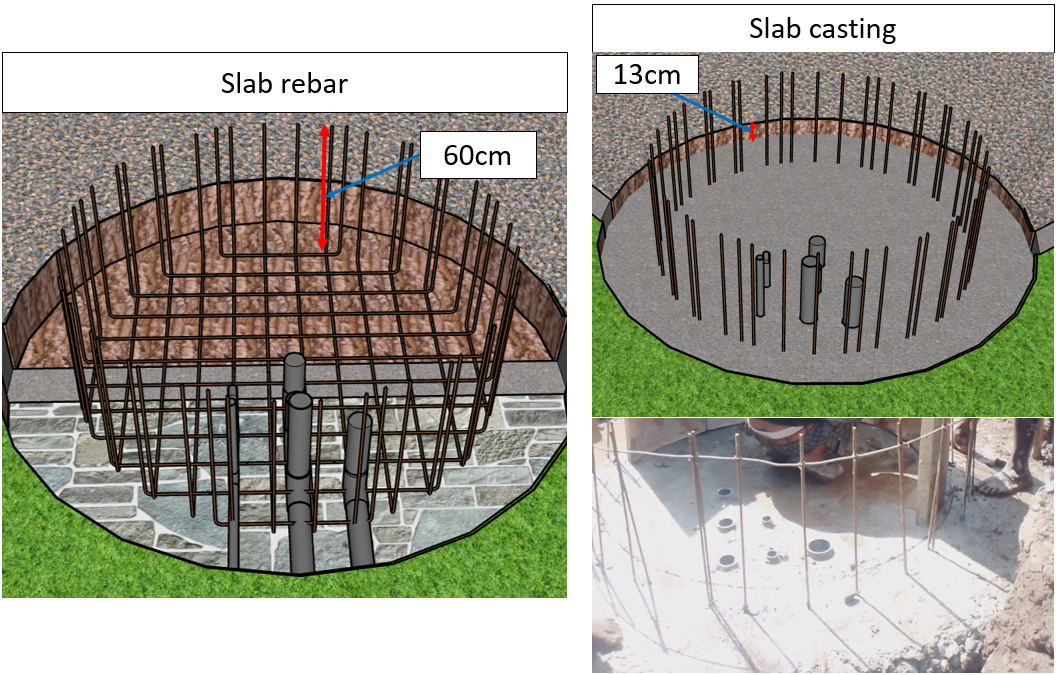
The rebar assembly used on the circular reservoirs (Mesh 20x20cm 8mm diam.) must be installed on the flat area prepared, but with 60cm vertical rebar instead of 40. Check Doc n° MF4-M50 “Mould reservoir construction” § Slab for more details.
Then a 10cm thick 1:2:3 concrete slab can be casted (at least, the slab should be 13cm under reference level 0) using the walls of the excavation as formwork. The top of the PVC fitting should be 1cm above concrete.
Spring box masonry work
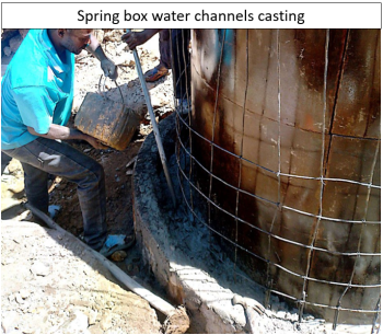
On the slab, downstream side, thin dressed stones wall (used as formwork) 30cm high and 15-20cm thick (mortar 1:3) have to be built around the box excavation (2.3m outside diameter). Upstream side, flat dressed stones (15-20cm thick maximum) 30cm high to be installed once every 2 steps of the rebar mesh (every 40-50cm).

Install the bottom inside part of a reservoir mold in the middle of the slab inside the rebar structure, and install two rows of horizontal rebar (every 20cm, 8mm diameter). The space between the mold and the masonry must be at least 15cm. Banana trunks must be installed between the flat stones, their dimensions must be chosen to fill as much as possible the gaps between flat stones, long enough to touch the mold and stick out of the masonry.
This preparation work is very important to build a water tight spring box it should be done with care. The next step is casting a 1:2:3 concrete wall between masonry and inside mold. This is where all the water will be collected and distributed.

Spring box walls
To finish the spring box, wall must be casted (1, 2 or 3 rings according to measurements done before). The method to cast it is similar to a reservoir using the bottom inside part already installed. 3 finishing steps are different:
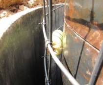
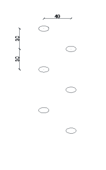
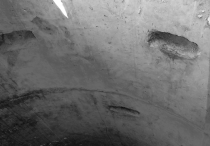
- Before casting the reservoir wall, reservation for the steps (ladder) need to be made. False banana trunk (~15 cm long, ~8 cm diameter) must be used, place them as would do steps (every 30cm high, 40cm between left and right). The trunk must be pushed tight against inside mold and if necessary attached with wire. After casting the false banana trunk must be removed and the steps chiselled for smooth contact.
- For the watering of the structure after casting, as it is not possible to fill completely the spring box, the wall and top slab have to be watered twice a day during at least 7 days and covered with a plastic sheet. Wet jute bags or a carpet of leafs if that is the only thing available.
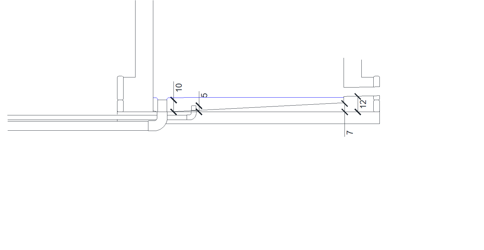
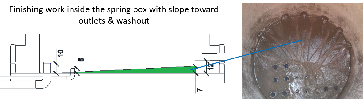
- The inside finishing work is different as you have a 12cm step between water channel and spring box slab. A gentle 1:2:3 concrete slope must be built between water channels and outlets/washout, it must be finished by light screeding (1:2 cement rich mortar) to smooth the surface. This has to be done after top slab casting and watering (to avoid damages on this finishing work).
If there is enough space in the box (the flow of water must not be disrupted), flat stones can be sealed in the finishing work to help the cleaning of the box without putting feet in the water:
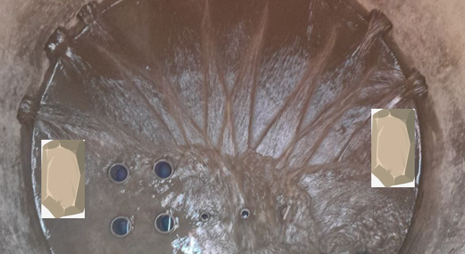
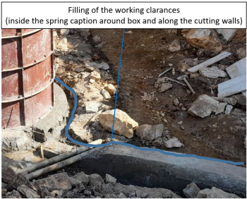
For details about the wall casting consult Doc n° MF4-M50 “Mould reservoir construction” § Wall casting. To finish the civil work on the spring box, cast with 1:2:3 concrete the missing part of the cutting walls (40cm long on both sides of the box. Then fill all the working clearances due to formwork upstream of cutting walls and box with selected materials.
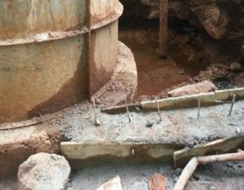
A washout erosion protection structure must be cast following: Doc n° MF4-M15 “General construction standards” § Washout erosion protection structure.
Filling & cover slab
To fill the excavation upstream of cutting walls, first ensure that no water remains trapped behind the box. It must be filled with big dressed stones up to 2-3cm under the cutting walls levels. To finish it must be filled with a last layer of gravels up to cutting walls level (to support the concrete casting for cover slab).
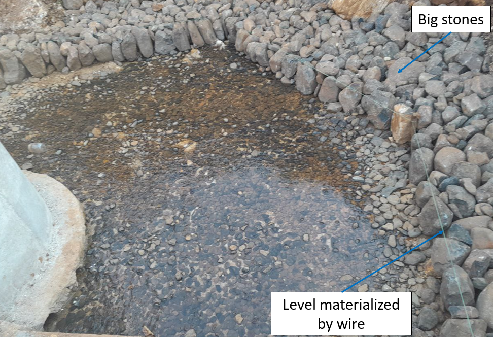
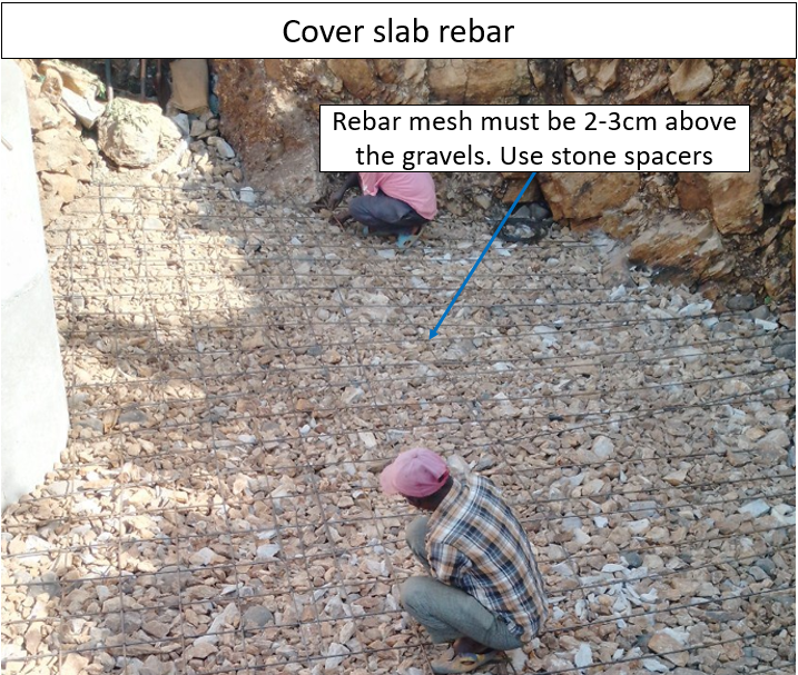
20x20cm 8mm diameter rebar mesh must be installed on the stone and gravel filling on all the cover slab area (from cutting wall to 20cm above the farthest spring eye). This mesh must be a 2-3cm above the gravels and attached with wire to the bended cutting wall rebar.
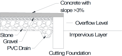
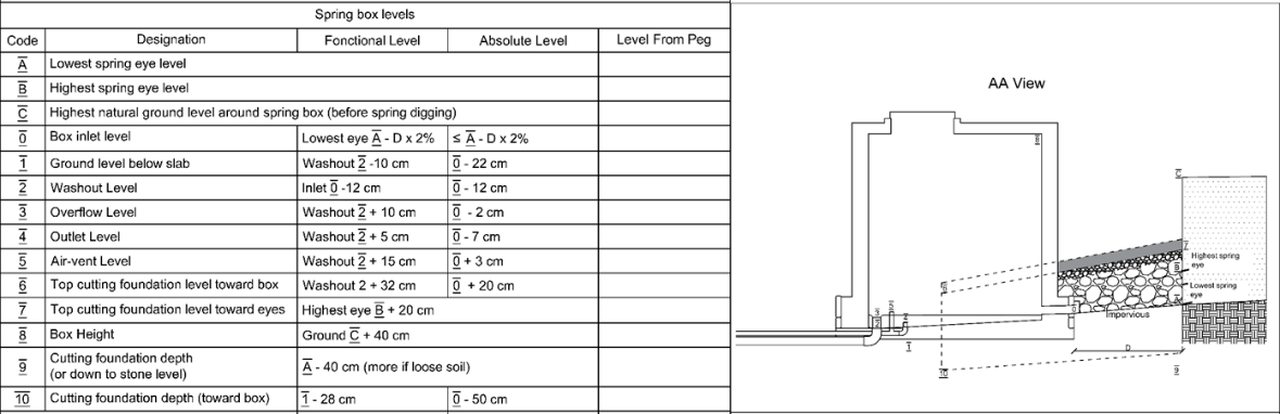
Finally, the concrete slab is build on top of the gravel layer, with 10 cm thickness. The level of the cover slab toward its upstream limit (7):
- If the highest eye is less than 50cm above the box inlet level, 7 is also the top of wall toward upstream limit of cover slab
- If the highest eye is more than 50cm above the box inlet level, 7 is not the top of wall. toward upstream limit of cover slab, the cover slab will have one or 2 slopes to reduce cost (less volume of concrete in the cutting walls)
Retaining walls
The last (but not least) work on the spring is to build retaining wall around the catchment for the sustainability of the structure. This step is crucial because bad choices can lead to big over costs.
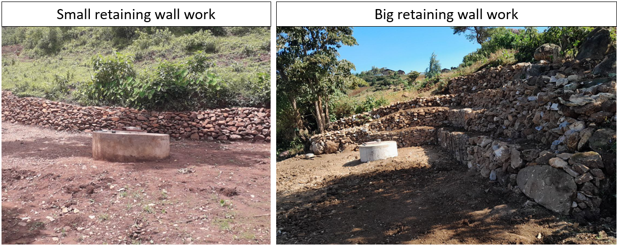
It is impossible to write a standard methodology for retaining walls because it is entirely related to the landscape of the catchment area (slope, type of soil, material available…). But some general recommendations can be applied in order of preference (see why in Doc n° MF4-M25 “Spring top slab height & water quality.
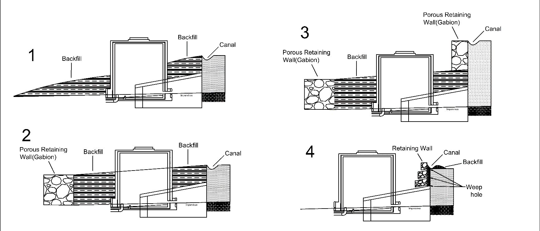
- Preferably, if the soil is not too lose (clayey soil) and the slope between top of the excavation and the level of soil downstream of the box is not too high (around 50%, i.e. 2 vertical for 4 horizontal meters), backfilling with soil is advised. It gives a better protection for the catchment1) and it is the less expensive type of protection.
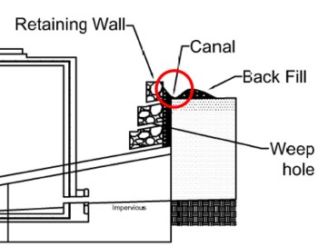
- Low retaining wall can be added downstream of the catchment to reduce the backfill slope. Use very permeable materials (dry stone, gabion) to let the infiltrated surface water seep through this retaining wall
- High retaining wall can be added upstream of the catchment when the slope between top of the excavation and the level of soil downstream of the box is too high, or when there is not enough backfill materials.
- Finally, if there is no possibility of backfilling, only retaining wall is acceptable but this offers the lowest level of protection.
In addition, some general rules can be applied:
- If possible use dry walls for economical purposes (dry walls can be built above masonry or gabions);
- Only solid rocky soils don’t need retaining walls;
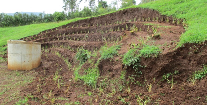
- Plant grass on contour lines:
> 
The total height of the retaining wall is defined as the vertical difference between the level below the spring box and the top of the excavation front. Depending on the site's topography, the design may consist of a single wall or a series of structures. The specific height of each individual wall and the soil type determines the most appropriate construction materials to be used. This chart can be used to help decision making for retaining walls.
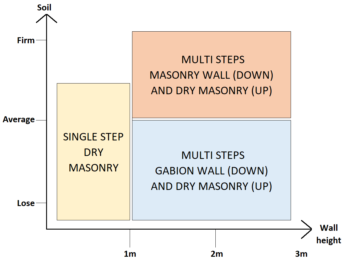
Masonry wall are acceptable only on rocky ground or concrete structure (most of the time the cover slab)
The final steps to ensure the sustainability of the spring area are:
- Diversion canal above upstream retaining walls at least 30cm deep (to avoid infiltration of rain water)
- A strong fence around spring inner perimeter (5m minimum around the spring box, see sketch below)
- Ideally a natural fence around outside perimeter (bushes, little trees…)
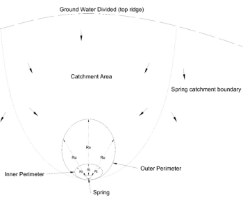
This steps must be implemented by the community and frequently maintained in the future.