

Table of Contents
Pipeline Protection
Generalities
HDPE Pipes
Maintenance-friendly gravity fed water schemes use HDPE pipes almost exclusively (PVC pipes for low slopes after structures). These pipes are less expensive, longer lasting, and easier to maintain and install but more sensitive to mechanical damage than GI pipes.
To compensate this weakness, pipelines need mechanical protection in all locations:
- Normal grounds (by trench)
- Rocky grounds
- Steep slopes
- Flat slopes after structures (PVC pipes or careful pipe laying)
- Crossings (rivers, roads, gullies)
- Additional structures (breathers, air vents, break pressure boxes and washouts)
The purpose of this document is to describe as thoroughly as possible all standards regarding pipeline protections construction depending on the above field configurations.
Installation
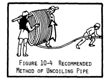
Protection should be applied during installation by taking extra care when handling coils of HDPE pipe. Deliveries must be as close as possible to the installation site because coils must be uncoiled only once (to avoid over bending) and pipes should never be dragged on the ground. Before installing the pipe, it should be carefully uncoiled while lifted up to avoid scrapping the ground. A stick can be used to that purpose:

Larger coils can be unrolled along the side of the trench, then carefully installed. Any dent or cut on the pipe should be removed and the 2 remaining parts of the coil coupled with an HDPE fitting. The pipe might need some time in the trench to flatten (up to 24 hours).
Trenches
The cheapest and most simple way to protect the pipes is to bury them in natural ground (considering that the ground allows hand digging).
To be effective, the recommended depth for the trench is 80cm to ensure there is always minimum 60cm of natural ground protection from the top of the pipe to ground level. The width should be kept to a minimum, 30cm for one pipe, if several pipes are in the same trench, the width is the sum of the outside diameters plus 25cm. Big rocks and sharp edges must be removed from the trench to avoid damage on the pipes after the filling.


Trenches slope must be regular and pipes must lay flat on the ground to keep this regular slope and avoid air blocks of the water.
Turns must be progressive to avoid pipes over bending that will led to leakages, no force should be applied to the pipe during installation. No coupling should be installed in the turn. Constructors advise a minimum bending radius of 20 times the outside diameter of the pipe. As a reference, below is a chart for a 90° turn:

Trench digging requires a big workforce so community mobilization is key. Delays on this activity can have a big impact on the contractor work plan, leading to increase of costs.
After pipe installation and inspection, trenches are filled with soil until it forms a 20cm high ‘donkey back’ shape bump covering the trench. This will ensure the trench remains fully backfilled after natural compaction and will not create a path for runoff that would lead to the erosion of the backfill. Fittings between 2 rolls of pipe must only be buried after 24 hours of service (after the pipeline reaches the downstream structure), to be sure that the connector is not leaking.

HDPE connectors installation
Between 2 HDPE coils, a connector must be installed. For small diameter pipes (⌀25, ⌀32mm) the method below can be used (every fitting must be carefully inspected before installation):
Open the connector and insert pipe through gasket, black gasket holder and white pipe holder. The pipe should be in contact on the stop of the connector body and finally the connector can be strongly tighten by hand
It is not so easy to plug HDPE connectors with big pipes (⩾ ⌀50mm), direct plugging of the pipe in the connector body with the gasket inside is not recommended (it may damage the gasket). The best procedure for this connection is a 2-step process described below. Every fitting must be carefully inspected before installation.

Before installing fittings, pipes must be cut and prepared with care:


Construction transfer
Each construction must be preceded by a construction transfer visit. This is a transfer from the designer of the network to the construction team formed by WWO construction expert, selected contractor and the Water Agent of the Federation.
Practically, these 4 people have to go from structure to structure following the exact pipeline route, marking it with pegs or painting on stable landscape elements (big trees, big rocks).
This visit is critical, especially for the pipeline, to know the details and locations of the selected route and additional structures and decide the special care to be taken in certain areas (specific grounds, erosion, crossings…). Areas at structure outlets sensitive to the formation of air pockets leading to air blocks also have to be identified and solution decided (PVC installation or not). The designer or construction expert will fill in the below format MF4-F73 “Pipe protection format” during the visit, listing these details for contractual purposes and as a reminder for the construction team.

This is also the moment to check the network sketch map and accuracy of all its information (pipes DN and PN, lengths, yields, DBs configurations). Example of sketch map data:


In every planned water point area, the exact position of all structures (reservoir, fountain, cattle trough, wash table) must be decided and pegged following chapters 3,4 and 5 of Doc n°MF4-M60 “Water point construction” § Orientation of overflow pipe in different scenarios. The format MF4-F62 “Water point configuration format” is filled in by the construction expert for contractual purposes and as a reminder for the construction team:

Finally this visit is the right moment for construction expert to prepare his schedule of control visits in agreement with the contractor following the Format n°MF4-F10 “Checklist plan for construction experts”:

- Spring excavation: 2 days (guidance and validation)
- Spring: 8 days (simple spring, larger spring may require Zone construction focal decision)
- Division box: 2 days (including pipeline leading to the structure ≤ 1km)
- Reservoir WP : 6 days (including pipeline leading to the structure ≤ 1km)
- Open flow WP: 4 days (including pipeline leading to the structure ≤ 1km)
- Additional Pipeline 1 km/day (when distance between 2 structures is ≥ 1km)
Summary of the transfer visit:

Control visits
Pipeline installation must follow the route used to design the network. During installation, justified route changes are likely, but the designer must be informed and must validate any change before implementation.
All trenches must be validated by construction expert before backfilling using format MF4-F72 “Pipeline construction supervision”. For every km of pipeline, the following characteristics have to be checked during the visit:
- Distance between top of the pipe and ground is > 60cm (at least 1 check every 100m choosing the most unfavourable places)
- Pipe DN and PN are as per sketch map (special care if DN is changing before next structure)
- Bottom of the trench is smooth, no rocky edges
- Contractor has constructed protections and additional structures as per filled MF4-F73 “Pipe protection format”
If all the controls in the checklist are compliant, the construction expert can allow backfilling. If not, construction expert has to organize a 2nd visit after giving his recommendations. The backfilling must exclude fittings and areas sensitive to air blocks: these will be backfilled after completion report is done as described below.
When the downstream structure construction is finished, it can be connected and water test conducted. The completion report MF4-F72 “Pipeline construction supervision” must be filled for the upstream pipeline to check the following characteristics:
- Checklists for every section (1km pipeline) have been completed and are compliant
- All backfilling is done with “donkey back” shape described in chapter 2.c
- 24h minimum has passed with downstream structure connected and no leakages on the fittings
- Crossings are finished and as per filled MF4-F73 “Pipe protection format”
- Breathers or air vents or BP box are finished and as per filled MF4-F73 “Pipe protection format”
- Air blocks have been checked with the following method:
- Open the washout of the upstream structure for 5 minutes to empty the pipeline
- The downstream structure yield must be over 50% of design yield after 20 minutes per km
- For example a water point with 0.2l/s of design yield that has a 2.6km pipeline must pass a yield of at least 0.5 x 0.2 = 0.1l/s after 20 x 2.6 = 52 minutes
- If this criteria is not met, pipeline route and air block sensitive areas might have to be checked. Guidance should be given by Zonal construction and design experts.
The completion report is mandatory to allow contractor payment for pipeline installation. All checked points of the report must be validated, or corrected by the contractor before payment. When the completion report is compliant, the last backfill is allowed (fittings and air block areas).
Challenging grounds
Rocky areas


Flat slopes after structures (PVC pipes)
The first meters of pipeline after a spring, a collection box, a distribution box or a DB on top of a reservoir can be identified as sensitive to air blocks by the design team (information also discussed during construction transfer visit). On this designated length of pipe, the designer can give 2 recommendations:
- Lay the pipe carefully: the trench follows a constant downward slope and the HDPE pipe is lain flat at the bottom of the trench
- Don’t backfill the trench until after final tests
- If indicated, install PVC pipes with level controls:
- Control slope of the trench with water tube level (minimum 1cm level difference every 1m)
- For every 6m PVC pipe section, control that there is slope with spirit level
Methodology for slope control with water tube level:
- Dig trench and install pegs:

- Install water tube, filled with water:

- Water level and 1% slope marking on the pegs:

Methodology to install PVC pipes:


Steep slopes
When the slope is steep (more than 20%) with no permanent vegetative covers (trees, shrubs), the trench should follow a “S” shape to decrease the slope. On each straight line, 3 half-moon shaped dry masonry walls are constructed (this construction prevents excessive erosion):


Crossings
Roads
To cross a road, bury the pipe 1m under the lowest point (drainage ditch if there is). This depth must be extended to at least 50cm beyond each side of the road. As this crossing implies an over digging, it must be anticipated to avoid a sharp slope in the pipe that can cause air blocks (10% slope maximum advised). The risk of erosion must be assessed depending on the level of compaction of the road, if necessary a GI sleeve must be installed.


Small rivers/gullies
To cross a small river or a gully that is not too deep (50cm max.) and has banks that can be dug and no signs of large erosion around, the pipe should be buried 1m under the river. Same principles as road crossing should be applied:
- Keep the depth 50cm beyond of each side of the river/gully
- Anticipate the crossing to keep a gentle slope on the pipe
- Assess the erosion risk and decide if a GI sleeve is needed


Big river/gully and big pipe: weir crossings
For rivers with a bed that is exposed to high erosion or that cannot be dug 50 cm deep, build a weir across the entire gully with a large spillway in the center, adapted to the rainy season flow. The pipe is buried with no sleeve upstream of the weir, 1m below the spillway.


Big rivers/gullies
If a river or gully depth exceeds 50cm and/or the banks can’t be dug, use anchored crossing. The suspension is a GI sleeve with 2 concrete anchors on each side, creating a bridge over the obstacle. The following characteristics are advised:

- Concrete anchors in 1:2:3 concrete (rebar structure to define with designer during transfer visit)
- Anchors should be at least 1 m away from the banks
- Anchors dimensions are decided with the designer during construction transfer visit and filled in the MF4-F73 “Pipe protection format”
- Consider the rainy season level of the river to be sure that the sleeve is at least 1m higher than the all year round

GI sleeve has to be extended under the ground until reaching 60cm of natural ground protection:


This type of crossing is limited to a 12m span, which is 2 lengths of GI pipe. If the crossing is over 6m, a 6m section of pipe must be installed in the middle with 2 sockets. This ensures the sockets are as close as possible to the concrete anchors, decreasing mechanical weakness. For example for a 12m crossing:

If the crossing is more than 6m, during transfer decide, with the support of designer, if the sockets need reinforcement (considering size of the pipe and length of the crossing). Here are 2 methods of welded reinforcement installation:


If needed the welding must be done before installation in the anchors. Longer crossings are not advised, but if there is no choice, a specific suspended bridge has to be designed by the designer. This case is out of scope for this methodology that focuses on typical cases.
Another solution for longer crossings is to dig as deep as possible in the river a 50cm trench and fill it with concrete. This is possible only if the bank is not too steep and diversion of the river is needed during the work to have a dry section of the river for the concrete. Step by step cross the entire river diverting the water as needed, of course it is better to work during dry season with less water to divert.

Special structures
Breather pipes
If a pipe section needs a breather pipe, pierce the HDPE pipe on the high point (or a little downstream if the high point is not clear) with a hot nail:

Then install a tapping saddle on the hole and connect a GI ¾’’ threaded pipe that must reach 1.5m above the ground. Drill a GI ¾’’ threaded socket at the top of the pipe to install a male plug:


If there is a stealing risk in the area where the breather pipe is installed (urban or remote area), a small slab can be installed above the tapping saddle with the following characteristics:

Automatic air vents
Like for a breather pipe, install a tapping saddle with a GI ¾’’ threaded pipe, but the length should only reach 10cm above ground. Then install the automatic air vent. A masonry box with the following characteristics with a metal door should be built around the air vent to protect it:

Pipeline washouts
Sometime a washout is necessary on low points with a risk of clogging, often before a gully crossing. Install a HDPE tee on the lowest point, then extend a pipe perpendicular to the pipeline down to a point lower than the tee (on a buried crossing this can be quite far). Install a HDPE adaptor, a short length of GI pipe, a socket and a male plug. To finish, the GI pipe should be anchored in concrete.


It is recommended to use the following assembly for the GI pipe before the drainage plug. Add 2 welded pieces of rebar inside the concrete to block the rotation of the pipe when removing the plug and avoid leakages inside the slab that are difficult to repair:
